How to Read a Metal Roof Installation Diagram
A metal roof installation diagram should show the roof deck or purlins, underlayment, panels, fasteners, and flashing at the eave, edges, valleys, and ridge. To use one, first check whether it shows exposed-fastener or standing seam panels. Then look for details at seams and roof openings, where water protection depends on the right parts working together. Ask your contractor whether the drawing matches your panel profile, roof structure, and local code requirements; a generic diagram is not an installation plan. For broader context on how these assemblies fit into residential construction, the Metal Roofing Alliance provides independent technical resources on metal roof systems and installation standards.
I’m Thomas Pruszynski, owner of TJ Builders & Developers Inc. Our team has worked on exterior projects across Northern Illinois for over 20 years, and I’ll help you understand what to look for in a metal roof installation diagram.
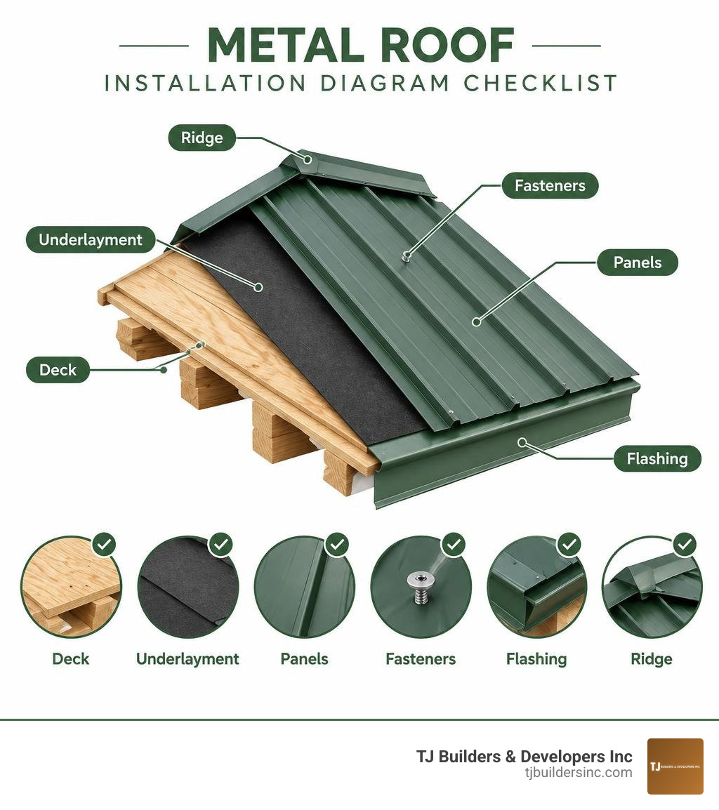
Metal roof installation diagram glossary:
Core Components in a Metal Roof Installation Diagram
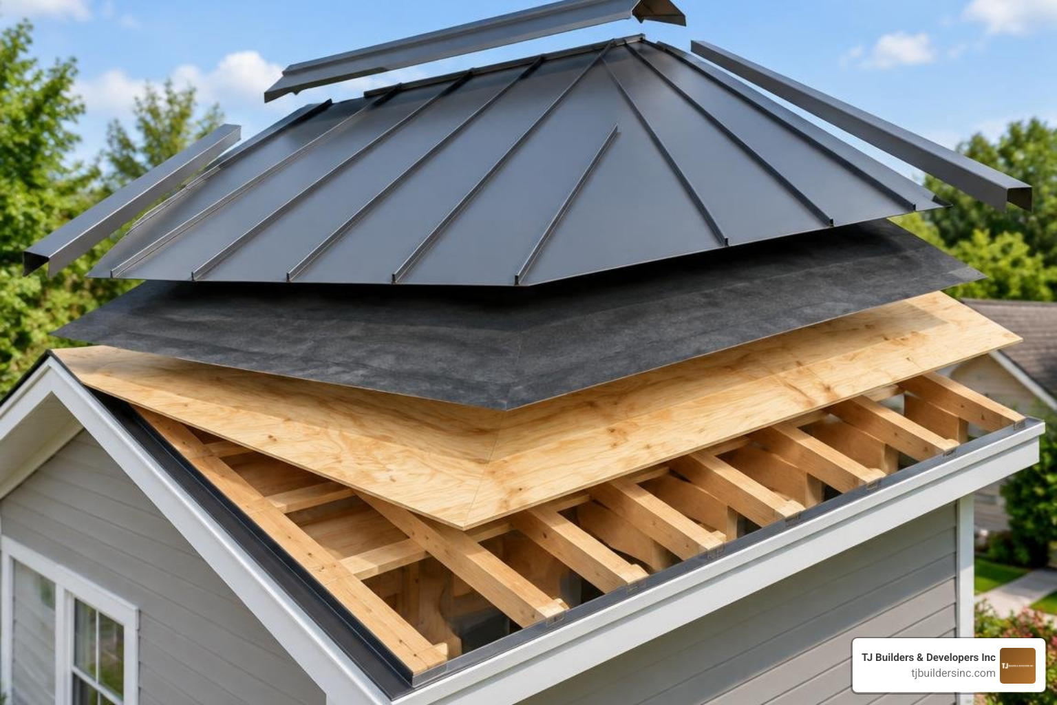
A comprehensive architectural schematic breaks down a roofing assembly into distinct layers that function as a cohesive barrier against wind, rain, and thermal transfer. Reading a technical drawing helps property owners understand why metal roofing systems are stealing the spotlight in modern residential construction.
Every detailed schematic illustrates five structural elements:
- Substructure Support: Solid decking or open structural framing that transfers loads.
- Underlayment Membrane: Secondary moisture barriers safeguarding the deck.
- Flashing and Trims: Formed metal transitions directing runoff away from joints.
- Fasteners or Clips: Mechanical hardware anchoring panels against wind uplift.
- Roof Panels: The primary weather-shedding surface layer.
Substructure and Underlayment Layers
The base layer in any diagram is the roof substrate. In residential framing across Northern Illinois, this is typically solid 5/8-inch or 1/2-inch CDX plywood or oriented strand board (OSB). For agricultural or post-frame applications, the diagram will specify open wood or steel purlins spaced at calculated intervals (such as 24 inches on center).
Directly above the substrate sits the underlayment assembly. High-performance schematics detail a self-adhering ice and water shield installed along the eaves, valleys, rakes, and around all penetrations. In cold climates prone to freeze-thaw cycles, building codes often require this membrane to extend at least 24 inches inside the interior warm wall line. High-temperature synthetic underlayment covers the remaining field of the roof deck, providing superior tear resistance and Class A fire-rated protection beneath the hot metal panels.
Flashing and Trim Profiles
Perimeter weatherproofing relies on precision-formed flashing components. An installation drawing highlights exact overlaps, hemming dimensions, and sealant placement for each trim profile:
- Drip Edge & Gutter Apron: Positioned along the eave beneath the underlayment or panel starter to lead runoff cleanly into the gutter system.
- Rake / Gable Flashing: Wraps the exterior edge along the roof rake to block wind-driven rain from penetrating beneath the panel edge.
- Sidewall & Endwall Transitions: Stepped or continuous flashings counter-flashed into vertical walls to manage water coming off adjoining structures.
- Valley Trim: Formed with internal diverter ribs to channel high volumes of converging water away from structural valleys.
- Ridge Cap Assembly: Caps the apex of the roof, integrating vented or solid closures to permit attic ventilation while stopping wind-blown snow infiltration.
- Butyl Mastic Tape: A non-curing, polyisobutylene sealant applied between overlapping trim profiles to create an airtight, hydrostatic joint.
Need Help With Your Home?
TJ Builders & Developers handles roofing, siding, gutters, windows, home additions, and fire damage restoration for homes and businesses in Lakewood, Crystal Lake, Schaumburg, and nearby McHenry County towns.
- Free, no-obligation estimates
- Licensed & insured
- 20+ years of local experience
Exposed Fastener vs Standing Seam: Metal Roof System Diagrams
Metal roofing systems divide into two mechanical categories: through-fastened (exposed) systems and concealed-clip standing seam assemblies. Understanding their distinct mechanical layouts ensures proper selection for longevity, maintenance, and architectural style.
| Feature / Component | Exposed Fastener Panels (Through-Fastened) | Standing Seam Panels (Concealed Fastener) |
|---|---|---|
| Primary Fastening Method | Color-matched screws driven directly through the panel face | Concealed hold-down clips or integrated fastening flanges |
| Thermal Expansion Handling | Restricted; relies on fastener washer flexibility and minor slotting | Free-floating; expansion clips allow longitudinal panel movement |
| Typical Panel Lifespan | 15 to 25 years (fastener washers require periodic service) | 30 to 50+ years (minimal surface maintenance required) |
| Recommended Minimum Slope | 3:12 (varies by profile and sealant design) | 1:12 (mechanically seamed) to 3:12 (snap-lock) |
| Common Residential Profiles | R-Panel, PBR-Panel, 5V Crimp, 7/8″ Corrugated | Snap-Lock, Mechanical Seam, Nail Flange / Nail Strip |
| Deck Requirement | Solid wood deck or open structural purlins | Typically solid deck with high-temp underlayment |
Through-Fastened Metal Roof System Diagram
Through-fastened systems utilize structural ribs—such as R-Panel, PBR, 5V crimp, or classic corrugated sheets—fastened directly into the roof substrate using hex-head screws equipped with elastomeric washers. When reviewing drawings for steely resolve and corrugated roof sheeting, you will observe that every panel relies on dozens of visible penetrations through the metal surface.
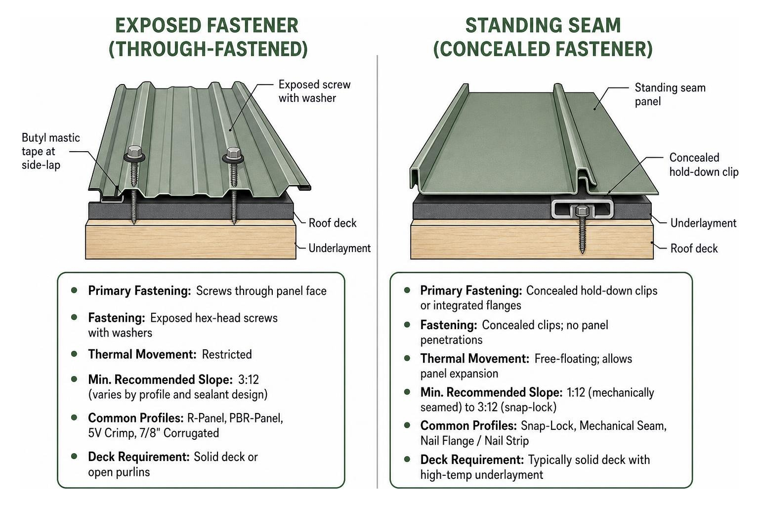
Because thermal expansion causes the metal sheet to expand and contract against fixed screw shafts, side-lap joints require continuous butyl mastic tape. Over time, thermal cycling places shear stress on the screw washers, making proper initial installation torque critical to prevent premature leaks.
Standing Seam Panel Schematics and Clip Attachments
Standing seam schematics depict a sleek, penetration-free panel field. To see a comprehensive breakdown of concealed systems, consult our standing seam metal roof installation masterclass.
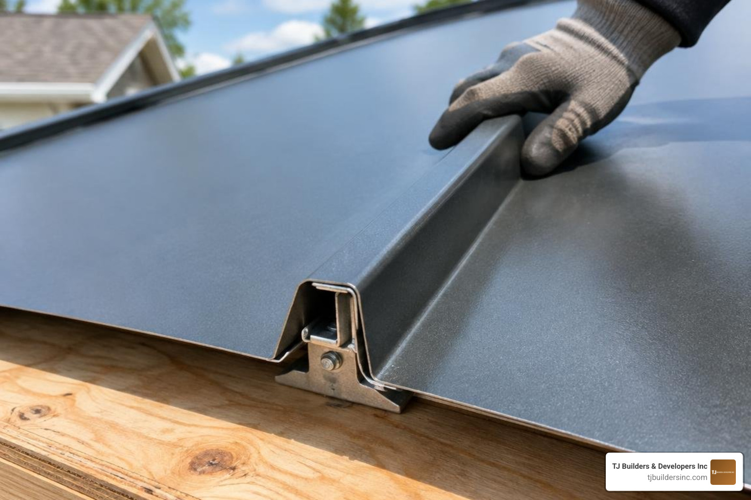
These drawings feature raised, vertical seams (typically 1 to 2 inches in height) that snap together or are mechanically locked with a specialized seaming tool. The panels are anchored to the roof deck using concealed clips:
- Fixed Clips: Fastened securely near the ridge or eave to pin the panel at a single structural reference point.
- Expansion (Sliding) Clips: Feature a two-piece movable tab that slides up to several inches, allowing panels up to 45 feet or longer to expand and contract smoothly across wide temperature fluctuations without buckling or distorting.
- Floating Ridge Details: Allow ridge cap trims to accommodate thermal movement beneath the cap without fatiguing the panel metal.
Fastener Placement and Washer Compression: What Diagrams Show
Engineering schematics show specific fastening patterns calculated to withstand extreme wind uplift forces and local environmental loads. The exact screw count per square (100 square feet) averages roughly 80 fasteners, but the layout varies across different roof zones.
| Roof Fastening Zone | Wind Uplift Dynamics | Standard Fastener Spacing Along Framing | Primary Layout Considerations |
|---|---|---|---|
| Zone 1: Field | Baseline positive/negative pressures | 24″ On Center (O.C.) | Uniform grid across interior roof surface |
| Zone 2: Rake / Eave Edges | Increased vortex pressure at perimeters | 12″ to 18″ O.C. | Closer spacing along perimeter trims to resist edge peel |
| Zone 3: Ridges / Corners | Highest localized negative pressure | 12″ O.C. (or double-screwed per rib) | Maximum fastener density around hip, ridge, and corner points |
Rib vs Flat Fastening Across Panel Profiles
A major detail in any fastening schematic is whether screws belong in the flat pan or through the high rib crown. Modern engineering standards dictate different rules for different panel profiles:
- R-Panel and PBR Profiles: Schematics specify placing fasteners directly in the flat portion of the sheet immediately adjacent to the major structural rib. This ensures the fastener pulls the flat pan tight against the structural decking or purlin, establishing a solid gasket seal.
- 7/8-Inch Corrugated Panels: Corrugated panels are often fastened through the top crown of the corrugation when installed over open framing, or in the valley flat when installed over solid decking with approved structural backing.
- 7.2 Western Rib Profiles: Feature wide, structural ribs that require screws placed on both sides of the rib base across perimeter framing, accompanied by #12 or #14 stitch screws along the overlapping side laps spaced no more than 18 to 24 inches apart.
Wind Uplift Zones and Project-Specific Requirements
Building codes require roof assemblies to pass standardized uplift testing (such as UL 580 or UL 1897 standards, designed to meet AISI specifications). When wind hits an exterior wall, it deflects upward and accelerates across roof edges, creating low-pressure vortices along eaves, rakes, and hips.
Engineering diagrams translate these forces into zoned fastening schedules. In Lakewood, Crystal Lake, and surrounding Northern Illinois communities, where winter blizzards and high-wind thunderstorms occur, local codes mandate adherence to enhanced perimeter fastening schedules. Fastener spacing that starts at 24 inches on center in the central field (Zone 1) tightens to 12 to 18 inches on center within Zones 2 and 3.
EPDM Washer Compression Diagram
Achieving the correct drive depth and washer compression is vital for long-term weatherproofing on exposed-fastener roofs. Ethylene propylene diene monomer (EPDM) washers provide exceptional UV resistance, but they must be compressed evenly.
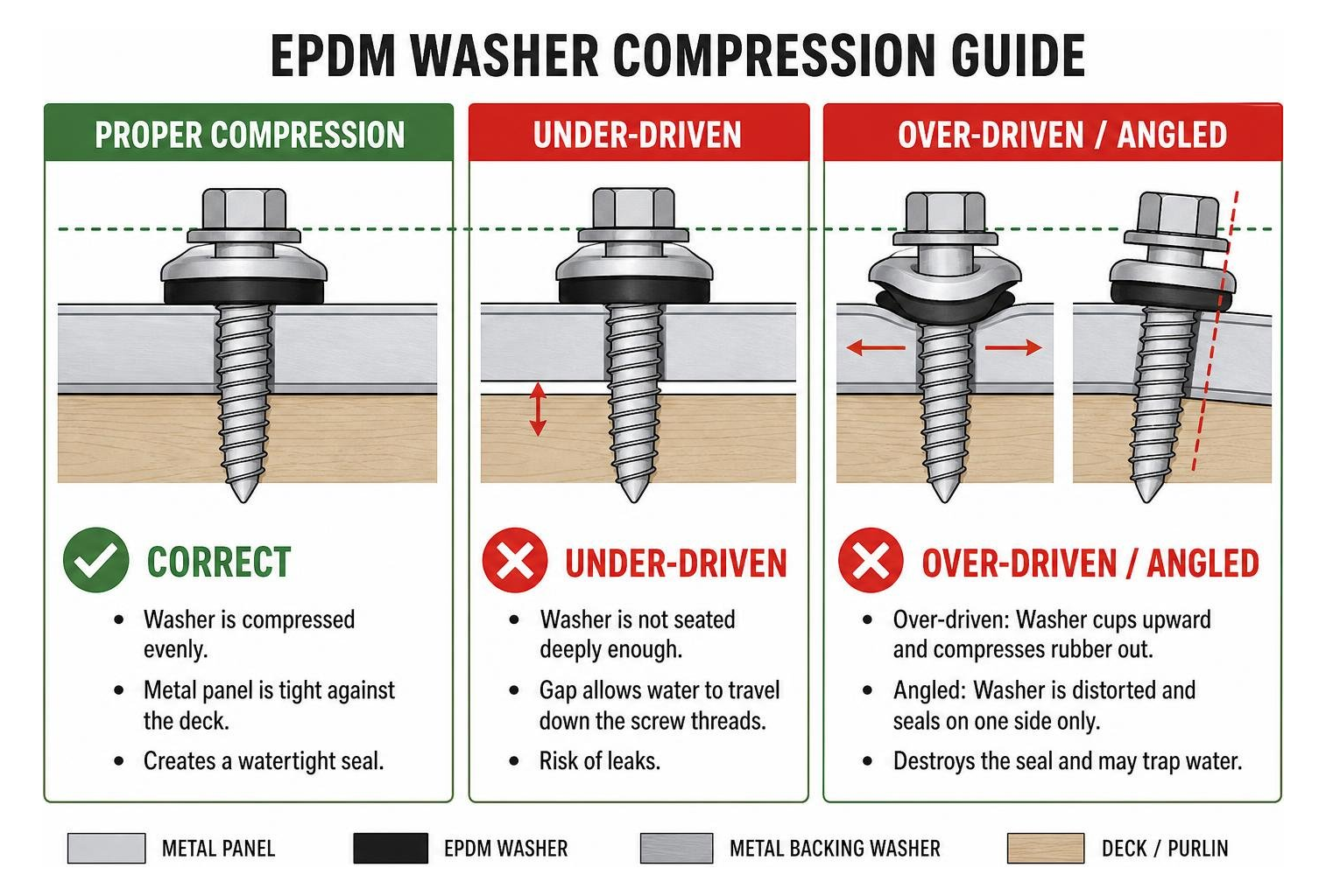
A technical fastening guide identifies three distinct conditions:
- Under-Driven: The fastener is not seated deeply enough. A visible gap remains between the metal panel and the EPDM ring, allowing water to migrate straight down the screw threads into the roof deck.
- Over-Driven: The screw is torqued with excessive force. The metal backing washer cups upward, splitting or squeezing the rubber gasket outward past the perimeter. This destroys the seal and creates a rim that catches standing water.
- Angled Fasteners: Driving screws at an angle distorts the washer, causing one side to over-compress while leaving the other side unsealed.
Trained roofing crews utilize clutch-driven screw guns with calibrated depth-sensing noses to ensure every fastener seats perpendicular to the roof plane with uniform 30% washer compression.
Panel Layout and Eave Baseline: Diagram Features
Precision layout prevents panels from running out of square across long roof runs. Consulting established residential metal roofing contractors guarantees that layout lines, overlaps, and edge allowances are verified before the first sheet is anchored.
Eave Baseline and Deck Alignment
The panel installation sequence begins with establishing a true 90-degree reference line:
- Squaring the Roof Deck: Using the 3-4-5 triangle method, installers verify that the eave line is square with the rake edges.
- Snapping the Eave Chalk Line: A primary alignment line is snapped parallel to the eave drip edge, maintaining a 1-inch to 1.5-inch panel overhang into the gutter line.
- Hemming the Starter Edge: For standing seam roofs, panel ends are notched and folded under using a hand brake to form a 3/4-inch hem that locks over the continuous eave starter flashing.
Metal Roof Panel Layout Diagram
Installation follows a strict directional sequence based on local prevailing winds:
- Wind Direction Alignment: Panels should be laid so that side-lap joints face away from prevailing winds, preventing heavy wind-driven rain from forcing its way under the overlap.
- Side-Lap Joint Assembly: For exposed panels, a bead of butyl mastic tape is laid along the under-lap rib before the overlapping sheet is seated. Stitch screws (#12 or #14 self-drilling fasteners) are then installed through the overlapping ribs at 12 to 18 inches on center.
- Ridge Clearance: Panels must terminate approximately 1 to 2 inches short of the roof apex ridge line to leave adequate space for attic exhaust airflow and thermal expansion.
Penetrations, Closures, and Ridge Caps
Roof openings and ridge terminations require specialized weatherproofing accessories:
- Solid vs. Vented Foam Closures: Pre-molded foam strips that match the exact profile of the metal panel. Solid closures seal out weather along eaves and rakes, while breathable, vented closures under the ridge cap allow attic air to exhaust freely while stopping insects and wind-blown snow.
- Pipe Boots (Dektite Flashing): Flexible EPDM or silicone rubber boots fitted over plumbing vent pipes. The flexible aluminum base ring is formed to the panel rib contours, bedded in continuous neutral-cure polyurethane sealant, and fastened with stitch screws at 1.5-inch intervals.
- Curb Flashing for Skylights: For heavy penetrations, detailed in our metal roof and skylight installation guide, fabricated metal curbs feature welded corner joints, backer plates, and cricket diverters to direct uphill runoff around the frame.
- Snow Guards: In snow-heavy regions like Northern Illinois, snow retention brackets are clamped to standing seams or fastened into structural framing to prevent sudden snow slides from damaging gutters and lower entryways.
Need Help With Your Home?
TJ Builders & Developers handles roofing, siding, gutters, windows, home additions, and fire damage restoration for homes and businesses in Lakewood, Crystal Lake, Schaumburg, and nearby McHenry County towns.
- Free, no-obligation estimates
- Licensed & insured
- 20+ years of local experience
Installation Quality and Substrate Considerations
Long-term metal roof durability relies on meticulous on-site craftsmanship. Addressing minor installation defects early prevents severe moisture damage down the road. For existing minor surface punctures, review our guide on how to fix metal roof punctures.
Fastening Across Wood vs Steel Framing
Different substrates require specialized fastener thread profiles and metallurgy:
- Solid Plywood or OSB: Utilizes #10 or #14 wood-drive screws with sharp Type-17 cut points and coarse, high-low threading for maximum pull-out resistance.
- Open Wood Purlins: Requires long wood screws that penetrate a minimum of 1 to 1.5 inches into solid wood framing.
- Light-Gauge Steel Framing: Requires self-drilling Tek screws with fine machine threading and hardened drill points capable of penetrating 16-gauge to 12-gauge steel purlins without pre-drilling.
Preventing Galvanic Corrosion and Oil Canning
To safeguard the roof’s structural integrity, installation drawings incorporate critical material-handling rules:
- Galvanic Corrosion Isolation: When dissimilar metals touch in the presence of an electrolyte (such as rainwater), rapid galvanic corrosion occurs. Steel panels coated in Galvalume (aluminum-zinc alloy) must never come into direct contact with copper plumbing pipes, copper gutters, treated lumber containing copper preservatives, or lead flashings. Non-conductive underlayment or neoprene barriers must isolate these materials.
- Swarf and Metal Shaving Removal: Drilling screws creates hot steel shavings (swarf). If left on the roof surface, these fine particles oxidize rapidly, creating unsightly rust spots that eat through paint coatings. Crews must sweep panels clean at the end of each work session.
- Preventing Oil Canning: Oil canning is a visible waviness in the flat areas of metal panels. While it does not represent structural failure, it detracts from aesthetics. It is prevented by ensuring the underlying roof deck is perfectly planar, avoiding over-driven fasteners, allowing adequate room for thermal movement, and selecting heavier panel gauges (such as 24-gauge over 29-gauge) or panels with striated ribs.
Frequently Asked Questions About Metal Roof Installation Diagrams
How do diagrams show fastener requirements for metal roofing?
Installation drawings depict fastener requirements through detailed cross-sectional views and roof plan grids. They specify screw diameter, point type, washer material, embedment depth, and center-to-center spacing across framing members. Diagrams will also highlight tighter fastener spacing within perimeter edge and corner zones to satisfy local wind uplift requirements.
Where do diagrams show screws on corrugated versus R-Panel profiles?
For modern commercial and residential R-Panels, diagrams show fasteners placed in the low flat pan directly adjacent to the major raised ribs, which provides rigid clamping against the substrate. For 7/8-inch corrugated panels installed over solid deck, screws are typically placed in the valleys, whereas over open purlins, drawings often specify fasteners placed at the crest of the corrugation to optimize water shedding.
What slope considerations apply to standing seam versus exposed fastener systems?
Exposed fastener panels typically require a minimum roof slope of 3:12 (a 3-inch rise per 12-inch horizontal run) to ensure fast water runoff across overlapping screw lines. Concealed fastener standing seam roofs with factory-applied seam sealant and mechanical seaming can be installed on low slopes down to 1:12 or 2:12 over solid substrate, as their continuous raised seams prevent hydrostatic water infiltration.
Reliable Metal Roofing Across Northern Illinois
A metal roof installation diagram provides an essential blueprint, illustrating how high-grade metal panels, underlayments, perimeter flashings, and engineered fasteners unite into a resilient, weather-tight system. However, transforming a technical schematic into decades of reliable shelter demands precision craftsmanship, calibrated tools, and strict adherence to local building codes.
At TJ Builders & Developers Inc, we bring more than two decades of dedicated exterior construction expertise to every residential project. From complete standing seam replacements to full exterior renovations—including siding, windows, and gutters—we deliver top-tier workmanship across Lakewood, Crystal Lake, Algonquin, Schaumburg, and surrounding communities.
To plan your upcoming roofing project with experienced professionals, explore our complete roof installation and replacement guide or contact our team to schedule a detailed on-site assessment.